Monday, December 19, 2016

Oven Fresh Nexus 5X

Woe and calamity. Yes, I got the dreaded Nexus 5X bootloop issue a couple of weeks back. Having thrown my phone in the freezer (inside a zip-lock bag) I got a boot out of it. That points to the issue being a bad solder joint. Maybe not in the general case but in at least mine. If your device passes a similar test you can try reflow soldering your device by following along below. Warning: this process will void any warranty you have, only do this as a method of last resort if Google or LG will not service your phone. You may also want to consider taking it to a professional electronics repair shop for reflow work.

With that warning out of the way and the freezer test having roused my suspicions I pulled the case off and took the motherboard out. iFixit has a great guide here for that process.

Time to cook!
With the motherboard out I inspected the teardown photos also provided by iFixit and determined which side of the board the packages (chips/black squares) I was interested in were on. The suspect package is the RAM. A Samsung K3QF3F30BM-QGCF with CPU the Qualcomm Snapdragon 808 conveniently located directly beneath it. The constant flexing of the phone in my pocket has most likely cracked one of the tiny BGA solder connectors off the motherboard underneath one of those packages.

Now that you have your motherboard separated from the phone's chassis preheat your oven to 195 degrees Celsius or 390 Fahrenheit whichever is appropriate for your current locale setting. While your oven is heating take out some aluminum foil and crush it into a ball. Un-crumple it so that there is still a rough texture as shown. This is going to help limit the heat transmission to the underside of the motherboard which we don't want to reflow. Place the motherboard on the foil and press it down. At this point attempt to get the board laying as flat as possible. You don't want parts sliding down the board on an angle if you overcook. Place the foil and motherboard on an oven safe cooking surface, a ceramic casserole dish will do nicely so long as it has a flat bottom, I used the spill tray from a waffle iron. So pick whatever looks good to you. Season with a twist of lemon and cracked pepper.

Now that your oven is up to temperature place the dish into the oven and start a timer for 6 minutes and 30 seconds. Wait anxiously. Note: If your oven is fan forced you may need to make an adjustment to the cooking time.

Remove your motherboard and let it rest until completely cool. Inspect the board for any physical damage, if you've really messed it up be extremely careful with reconnecting the battery. Who knows what you might have shorted out.

Reassemble your phone following the guide from iFixit and give that puppy a charge. Power it up and hope for the best!

Friday, July 15, 2016

Minolta 7000 Battery Upgrade MK2

So my last post was about building a replacement battery pack for the Minolta 7000. Since then I had a much higher quality 3D print made of the housing with some lessons learnt from the first version. This is the result.


This part was ordered from Shapeways and I'm quickly learning that they are so far ahead in this game that you should just go to them straight away. Incidentally you can buy this part from there if you want to build this.

Need some help building that? Well tough luck! I present to you the world's worst build log. Seriously everything that could go wrong with this video went wrong. I don't think I even build a single thing on camera.


So I might not be a videographer but you have to admit the end product looks pretty nice.


Monday, May 23, 2016

Minolta 7000 Battery Upgrade

Say you've got one of these Minolta 7000 cameras. Great camera. Just one problem. Whenever you pick it up the batteries are flat. You've lined up your shot, you press the shutter button, the mirror flips up and nothing happens.  


What you need is something a little more reliable than these original battery grips. The piles of dead AAA and AA batteries get a little annoying after a while. 


The solution as I see it is having a rechargeable battery with a built in charge controller. This means the camera can constantly sit on power while it is at home. Always 100% charged ready to run a few rolls of film. Luckily the engineers at Minolta made this battery pack design very modular and with quite a simple electrical interface. First order of business is to model the battery holder so that we don't have to destroy an original part. 


You can note the that this design doesn't have any ports or holes. This was because it was being produced before I had the rest of the components in hand. Speaking of components these are the parts that you need:
  • TP4056 based charge controller
  • A lithium battery (This one fits easily)
  • A couple of 3mm LEDs why not buy 30!
  • Some brass rod to make your contacts. Springs would be even better but good luck buying two of those for anything less than $10. I cant justify that to myself somehow.
  • And finally some jumper wire for connecting everything up.


Implementation time! It is a really simple setup. Simply solder the battery to the appropriate terminals. Desolder the existing LEDs from the PCB and replace them with the new 3mm ones. I used the jumper wire to make a flexible connection here. Now drill and rasp out the holes in a spot that you like. The top side of the new battery grip makes the most sense because the camera can sit flat while you are charging it and your hands won't come in contact with the ports while you use the camera.
Here is the result of this build out. I've filled a lot of the grip with Sugru. This fixes the components in place extremely solidly. This is particularly important for the charge controller as it has to stand up to the force of repeated USB connection and disconnection cycles. The Sugru was also used to fill up void space from the imperfect fit of the part. If you want to do this simply brush vegetable oil onto the side of the void you want to fill attach the Sugru to the other part and press both sides together until they mate the way you want them to.

One thing to note is the green pin. I originally missed this part. It is used to separate the memory backup battery inside the camera from the circuit when the battery pack is connected. Forgetting this will cause your battery to attempt to charge this little 3V lithium cell which could go badly. Another option is simply to take the backup cell out since you wont need to detach the new battery grip ever again. Luckily the new grip looks much better on the camera than it looks inside.


Of course there were a few lessons learned along the path of this build.

For a start voltage wise the camera will accept 4.1V and nothing lower. Below this point it automatically shuts down when you press the shutter button. This was tested on a beefy bench power supply so it's not the battery that causes this behavior. The camera draws about 1.1 amps during it's shutter actuation and frame winding. This load is for a roughly 200 milliseconds. It then returns to it's quiescent draw which is very low. Oh and before I forget the metering system and the LED backlight for the viewfinder together draw around 300mA when they are on. The AF motor also draws around 1 amp.

 
On the topic of current you need to make sure that your battery and current protection circuit will supply just over an amp to the camera at peak load without tripping a short protection feature. This makes small AAA size cells with inbuilt protection a bad choice.

Earlier I said the camera only accepts >4.1V with the factory manual suggesting a max voltage of 6V be applied to the camera. So how does it work on a LiPo battery, don't they have a voltage of 3.7V? Well not quite they have a nominal voltage of 3.7V their discharge curve is shown to the right. Luckily for this project it starts at 4.2V. Clearly it drops very quickly to the nominal voltage under discharge. However we are using so little of the battery's capacity this is not an issue in practice.

One thing I learned a particularly hard way about the Minolta 7000 is that they have an internal fuse. The fuse is located inside the hand grip hidden under a film of tape and is formed by a PCB holding a single strand of fuse wire. There is a diode setup to short circuit the battery across this fuse if the polarity is reversed by accident. It's quite a smart setup because in the normal mode of operation you aren't incurring any losses. So if you aren't getting any response from one of these cameras it is a good thing to check before disassembling the entire thing like I did. You can access it by removing a few screws at the bottom of the body and a few inside the front of the grip.


Thursday, May 5, 2016

3D Printing Round One

I've recently gotten excited about the use of 3D printing. Maybe I'm late to the game because the cost of entry outside the USA is much higher. Maybe because I have good luck building things the old fashioned way most of the time.

Anyway 3D printing or maybe more accurately additive manufacturing is an amazing technology. You can produce complex shapes for practically the same price as a solid block of material. That is the magic thing about it. If you make a more complicated part with less material the price comes down. I've automatically been in the mindset that the more geometrically complex a part the more work goes into producing it. That just isn't true anymore.

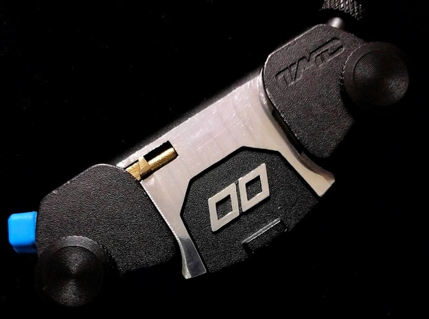
Of course the other thing that 3D printing is enabling is personalized design and low volume production runs that wouldn't be worth doing using traditional systems. For instance I purchased a camera clip (reviewed below) which wasn't in my opinion up to the job it was designed for. The reason? A single part made with too poor a tolerance.


Previously I would have either thrown this out or tried to solder together a replacement part myself. Instead I decided to finally learn how to use a CAD package with some degree of confidence. So I pulled down a copy of 123Design and got cracking. A couple of hours later I had this


Not that much to look at but it seems about right. Oh and I should say I measured the original part with this.


So based on those shaky measurements and some guessing that people probably make things in integer numbers of millimeters I pushed the model file off to and Shapeways & 3D Hubs. You can actually do this with a couple of clicks right out of 123Design which is very much appreciated. Two weeks and one week later respectively I had the following parts on my table. The original in the lovely blue on the left and three of the replacements on the right. Obviously the stand out part is the bronze infused stainless steel. It's incredibly tough. You could make just about anything out of this material. One word of warning. It's difficult to post process. The bronze fouls your cutting tools and the steel has a very high temper on it. Maybe this should be the new standard for bike locks? 


This is how the new part looks in situ. Pity about it clashing with their colour scheme.


Here it is securing my rather heavy camera. Far more trustworthy than the plastic part!


Now the part that I find the coolest. If you happen to want this incredibly obscure part you can just go here and have one run off the printers at Shapeways for you. In fact two people have already done that. Isn't that cool? Yes. yes it is.

Tuesday, April 26, 2016

OpenMemories DoF


A quick (and ugly) sample app doing something slightly useful using the OpenMemories-Framework https://github.com/ma1co/OpenMemories-Framework

APK available here https://github.com/Bostwickenator/dof-math/releases/tag/1.0

Amazing work everyone involved!

Saturday, April 2, 2016

IoHeating Part 2

Last time we built an internet connected heater with a REST interface. Being able to control anything physical from a web browser is cool. Being able to control it from your phone is much cooler.
Something like this

This post is about doing that. Let us not waste any time. Open up a copy of the GitHub repo. Even better pull it and open it in Android Studio


The core of this application is the communication with the Particle.io device via their API. What I have chosen here is a compromise for time. We aren't using the normal method of authentication that you would take if you are releasing a product to a consumer market. Simply we are taking our credentials and building them into the application package. This means anyone who has access to that application package can control your device. You've been warned. On the positive side of this trade off the code is really easy to understand and doesn't require a lot of interactions with authentication APIs. 

The system we are using here is Bearer Authentication and part of OAuth2.0 spec. Conceptually it is a simple two part process. Firstly you the user authenticate to a server. You then say to the server. Give me a secret so big that no one can guess it. This secret is understood by the server to mean (since no one can guess it) that any other actor (program in our case) that knows the secret is authorized by you to do things on your behalf. The second step is exactly that you give a program the secret and it talks to the server to do work for you. We are simply breaking this up and doing the first step in our development environment so that we don't need to write a UI for it in our application. Particle has a detailed write up of how OAuth2,.0 works should you be interested. 

If you haven't already you need to setup the Particle.io command line interface. Then from the CLI you can use the command. 

particle token new

to generate a token for your application.

There is a second slightly hacky method you can use to obtain a token which is pulling one out of the Particle build system. Open it up and navigate to the settings screen. You should see a token in place of the red square below. This has the advantage (and security issue) that it will not expire. You can also generate longer lived tokens using curl and performing REST calls to the Particle servers. 


You can now use the particle dashboard to find your device ID. Or the CLI if you are so inclined.

Substitute these values into the application (removing the square brackets) and you should be able to communicate with your device.

The Android app show a few patterns for working with this API. As it is a simple application with only a few functions we aren't implementing a service or any more complicated Android patterns. We just use the AsyncTask API.

So that is it. Really simple communication with your development device suitable for your simple use cases like controlling your own device with a bespoke app.

As an added bonus. There is some nice color animation depending on the heat. OR whatever you what to retrieve from your device.

Thursday, November 5, 2015

IoHeating Part 1


Recently I had a few days off from work and decided to solve one of the problems that had been bothering me throughout winter. Namely a cheap heater which had a temperature dial that was:
  1. Completely unlabeled
  2. Driven by a large loud low accuracy thermostat.
Instead of solving these problems by getting a new heater or off the shelf controller I decided to make things a little more interesting. That meant it was parts shopping time. 

If you are switching mains power you have two options relays and triacs. Triacs are a sextuple layer silicon switch similar to the better known transistor but compatible with alternating current. They are great because you can switch them many millions of time with no wear and because they are completely silent in operation. Relays are simply electronically operated physical switches. A triac would clearly be optimal here. A quick Google later and it turns out that the majority of parts for the hobbyist market are based around relays. I wanted to utilize one of these readily available parts because:
  1. When I have time off work I'm trying to be as lazy as possible
  2. Relays and triacs often need a drive transistor which I would have to solder on veroboard (eww)
  3. Isolation.
In New Zealand we use 240V AC in every country the AC transmission voltage is dangerous, here especially so. Isolating the low voltage electronics especially the controller (more on that soon) is important for safety and longevity. Fortunately electrocuting kids is very bad press so most of the hobbyist relay boards include a drive transistor AND an optoisolator. If you haven't come across these before I'm about to make your day.

Optoisolators are essentially a transistor where the gate is not electrically connected but optically connected. So on on side of the package you have an LED and on the other a transistor with a gate that is excited by photons not those dirty old electrons. This whole thing is packaged up in a nice black box that puts the input side far enough away from the output side that everything is electrically isolated and safe enough to lick (do not lick). We are actually using the same power supply for driving the relay and the controller so this doesn't actually make us all that much safer but it is still good to isolate our delicate IO lines from nasty physical things like relay coils.

Something like this.
So we have a switch that we can control. Now we need to know when to turn the heater on and off. The clunky old thermostat relied on a bimetallic strip to sense the temperature of the room. This sensor if you want to call it that is large and has an inherent hysteresis. We can do better. How precise does our temperature need to be half a degree you say? Perfect we'll use the DS18B20. This is one of the first digital parts I ever utilized. They are a robust, decently accurate, and voltage compensated sensor. Even better you only need a single IO line to talk to them due to the exceedingly well named "1-wire protocol". 

Finally time for the controller! Particle (previously known as Spark) are a group who have developed a seriously amazing little bit of kit. The Photon dev board. To boil it down. ARM microcontroller, WIFI 802.11n, Cloud API and development platform, ludicrously simple code and integrations, $20. Go and buy one right now.

So with our shopping list complete let's build our thing. Just so you know a couple of additional components will probably come in handy, those are.
  1. A heater with some space in it
  2. A power supply for your controller
  3. A high temperature insulation. Don't use heat shrink this is a heater. Instead use Sugru

With that the beautiful build is revealed! From top to bottom we have. A USB power supply from a hapless phone and behind it the Photon board. Below that we have the original heater switches and the thermostat. At the bottom you'll see the relay board and the actual heating elements. The relay board has been tapped into the AC power such that it can break the circuit to the heater whilst leaving the Photon board powered (clever huh). It is also wired in such a way that all the heater's original safeties are in place. The original thermostat (turned up to full), a thermal fuse (in between two of the elements you might spot it) and a thermal cut off at the other end of the element which isn't pictured. Also not seen the the DS18B20 as that is carefully located outside the case as to make it less susceptible to heat soak from the heater chassis. There are more pictures of the build here.


The genius of the Photon dev board is just how easy it is to step integrations between real world items like our heater and the world of data. For this project I used the build.particle.io development platform and whipped up a simple firmware that knows how to turn the heater on and off, how to measure the temperature from our temperature sensor.

There were a couple of small complications discovered whilst writing the code.
  1. I didn't read the datasheet for the DS18B20 temperature sensor quite well enough you need to use a pull up resistor to get the 1-wire communication working with the Photon. No issue that five minutes with a soldering iron can't fix.
  2. Our relay board likes to turn on but doesn't like to turn off. To deal with this one we can get away with setting the IO line to INPUT_PULLDOWN this soaks up any stray electrical potential and makes sure the relay optoisolator and thus the relay returns to the off state.
Want to have a look at how simple this was to implement or even spare yourself that effort and copy it for your project? Go right ahead and read this gist of heater code. Just remember that you'll have to use the library include system in Particle Build to add the libraries listed at the top of the source.


At this point we have a heater that can turn on and off at the whim of anything that can use a REST protocol. While using a web browser to turn a heater on and off is pretty cool that isn't going to cut the mustard in this connected world. What we need is apps! lots of apps. Well maybe just one. Next post I will tell you about the application below.